

Network teaming capabilities within vSphere exist for more than just the potential of improving performance. Its ability to provide redundant connectivity in the event of a discrete failure of a Network Interface Card (NIC) or a switch makes it a requirement in any production environment. But this does not happen automatically. Designing for failure requires an understanding of how to properly cable hosts to switches, and configure the hypervisor to account for various failure conditions.
While this may sound obvious to some, it is not unusual to see an environment that experienced a failure condition larger than necessary only because basic configuration practices were not implemented. Since vSAN is a distributed storage solution, the network configuration of the hosts to account for failure conditions is critical to the availability of data. The configuration topics below serve as a reference point to ensure your vSAN environment is configured in a resilient way.
The concepts described here build off the information found in the posts: “vSAN Networking – Network Topologies,” “vSAN Networking – Network Oversubscription.” “vSAN Networking – Optimal Placement of Hosts in Racks” and “vSAN Networking – Teaming for Performance.” Further information on vSAN networking may be found with the vSAN Network Design Guide. For VCF environments, see “Network Design for vSAN for VMware Cloud Foundation.”
Accounting for a NIC Failure
Hosts must be able to maintain connectivity in the event of a NIC failure. At minimum we will need to meet two conditions:
- The host must have more than one physical NIC. While modern NICs found in servers will typically have 2 to 4 NIC ports (also known as uplinks), this alone will not give you redundancy if a NIC fails. Occasionally a discrete NIC port can fail, but most of the time it is the entire NIC that fails, hence the need to have more than one NIC per host.
- Proper configuration of the virtual distributed switches (VDS). The VDSs for the host must be configured so that VMkernel interfaces and VM port groups that reside in that VDS can fail over to another port on another NIC in the event of a NIC failure.
For example, in the figure below, we see the back of a host that has two NICs each with two ports. Each VDS consists of two uplinks. While the VDS itself can have both uplinks as active, the specific VMkernel interfaces created within a VDS can be configured to override this setting. In this example we will use Active/Standby using “Route based on originating virtual port ID” as described in the post: “vSAN Networking – Teaming for Performance.” For the VMkernel interface tagged for vSAN, vmnic3 is set as active, and vmnic1 is set for standby. The VMkernel interface tagged for vMotion is also in the same VDS, but its active and standby uplinks are reversed to utilize resources best. If the NIC on the right-hand side of the illustration fails, then the vSAN services will fail over to the standby uplink on the remaining NIC.

Figure 1. NIC failure and failover of a vSAN VMkernel interface over to the standby port in the VDS.
In the example above, a single VDS containing all of the uplinks could have been created instead of two separate VDSs. There are tradeoffs to both approaches, but creating multiple VDSs with only two uplinks across both NICs may be easier to understand which uplinks are used with a specific VMkernel interface. It helps ensure that the active and standby uplinks always come from two different NICs. A single VDS containing all of the uplinks can be prone to an administrator accidentally selecting the active and standby uplinks coming from the same NIC.
Accounting for a ToR Switch Failure
Redundant networking uplinks provide more than just resilience in the event of a NIC failure. If the uplinks associated in that team are cabled correctly, where each is connected to a different ToR switch, then the hosts can also remain available in the event of a ToR switch failure.
Switches are devices that fall outside of the control and management of the hypervisor, so failure detection typically relies on the link status of the uplink on a host connecting to the switch. This type of failure detection only works with switches directly connected to the hosts. For more sophisticated detection of switches not directly connected with the hosts, beacon probing can also be used.
The behavior of a vSphere host will largely be the same for a switch failure as it will be for a NIC failure. The services using the uplinks connecting to the failed switch will failover to the uplinks connected to the available switch.
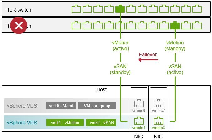
Figure 2. Switch failure and failover of a vSAN VMkernel interface over to the standby port in the VDS.
Proper handling of a switch failure requires the proper cabling of the active and standby uplinks to their respective ToR switches. If the active and standby uplinks are cabled to the same ToR switch, a switch failure would isolate the host from communication to the other hosts. Cabling the uplinks properly also ensures that intra-cluster vSAN traffic stays within the ToR switch, and does not traverse the spine.
How long does it take to detect a failure and fail over to the other uplink? The actual time will vary depending on the circumstances, along with the teaming method used, but with a link status change, the failover may be well under 1 second.
Recommendation: Enable CDP/LLDP on your VDSs in your environment. It is a nice way to self-document what physical switch ports are used by the host uplinks. It takes very little effort, but can offer valuable information about your network topology.
Performance Degradation During NIC or Switch Failures
A vSphere or vSAN cluster is a collection of shared hardware resources. When there is a failure of something like a NIC then you have the same amount of workload demand potentially going over fewer resources. What is the best way to account for these types of failures? Here are some options
- Use Network I/O Control (NIOC). The use of NIOC in vSAN paired with the appropriate settings helps prioritize vSAN traffic specifically in failure conditions, where vSAN VMkernel traffic is merged with other traffic types to a new uplink.
- Spread out services and workloads evenly across uplinks. If you have two, 2-port NICs, distribute the various VMkernel interfaces and VM port groups across the available NICs as evenly as possible. Also envision what that looks like in a non-failure and failure state to see if that makes most sense.
- Increase the number of uplinks. If you design for the best possible operational state under a NIC failure, you may determine that you need more uplinks to satisfy this requirement.
- Use higher bandwidth links. The use of higher bandwidth uplinks will help reduce the need for a higher number of uplinks in your hosts. For example, two 100GbE links can provide the same bandwidth as eight, 25GbE links. It also has the benefit of reducing the network port consumption on the switches.
Gray Failures
Not all failures are clear, permanent and distinguishable. For example, some NIC ports will experience an oscillating status change of their link state – sometimes referred to as port flapping. Other NIC ports may experience issues with Ethernet’s ability to automatically negotiate the highest supported speed between a NIC and a switch, with ports randomly dropping to a much lower supported speed without throwing an error. These issues can be caused by bad firmware on the NICs, drivers, or by physical link issues.
The intermittent nature of these types of issues may make them difficult to detect. Awareness of these types of issues are especially important for vSAN because of its reliance on the network to store data resiliently. Undetected, non-binary failures often only expose themselves only as a performance issue where a VM may see unusually high latency. What can be done to expose these types of matters more clearly? VCF Operations for Logs can easily expose these types of log events that may otherwise go unnoticed.
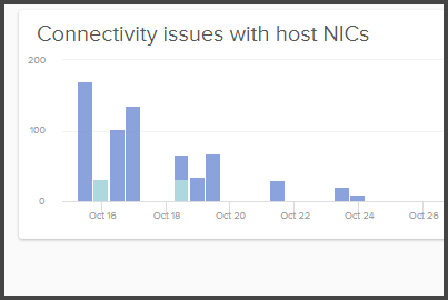
Figure 3. Detecting connectivity issues with host NICs using VCF Operations for Logs.
Further information on vSAN networking may be found with the vSAN Network Design Guide. For VCF environments, see “Network Design for vSAN for VMware Cloud Foundation.”
Summary
Your vSAN hosts should use redundant NICs connected to redundant switches paired with a proper VDS configuration to ensure that your vSAN hosts can maintain proper connectivity during network related outages.

